Next-Hop Routing
Next-Hop Routing provides a graphical representation of next-hop entries in route tables. This provides you with an easier means of understanding system-level routing across their networks.
A path in the Next-Hop visualization is a set of edges that describes the route from the source point to the destination. Endpoints in the topology can be one of three types: interface, network, or node. A network interface on a device loaded into the system can be the source or destination point of the routing algorithm. An IP network connected to an interface loaded into the system can also be the source or destination point of the routing algorithm. The third endpoint type, node, must be an IP address of a node that is contained in a network loaded into the system. If the node address does not exist in a network in the system, the node cannot be used as a source address; no routing will be performed in this case. If the node is a destination, routing will progress to the last device in the system that can route the packet, and the node will be represented by a “missing node” object.
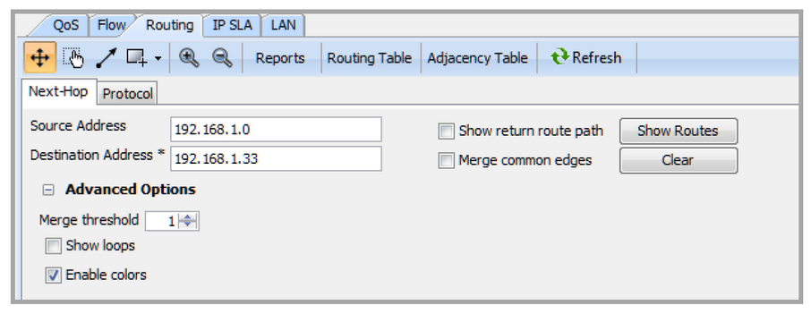
To access Next-Hop Routing visualization, click on the Routing tab. Below the system topology toolbar, select Next-Hop.

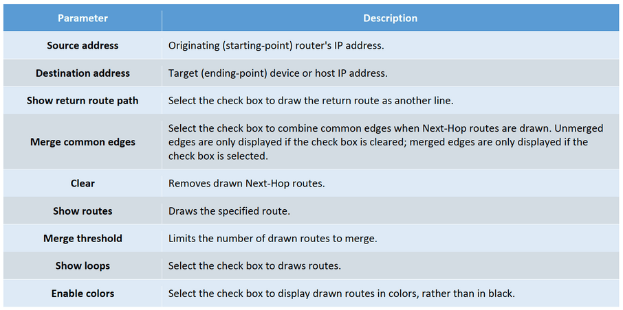
Use the parameters below to set up Next-Hop Routing. Click Show Routes to execute Next-Hop Routing visualization, or click Clear to reset the view.

Next-Hop Routing visualization in the system topology view is displayed as a bold, light purple-colored line. If the destination address is not represented in the current set of network devices, as in the example below, a new icon representing the destination device is created.